|
TABLE OF CONTENTS
DIY Robotics Introduction
1. DIY Robotics Overview 2. Using The Robot Program 3. Introduction to Robotics 4. Developer Kit Box Contents 5. Battery Care & Charging 6. Powering Your EZ-B v4 or IoTiny 7. Using a USB Wi-Fi Dongle 8. Serial/USB Connectivity 9. EZ-B v4 & IoTiny Datasheet & Communication Protocol 10. WiFi Client Status on Digital Port 11. Firmware Upgrade 12. 360 HDD Servo Overview 3D Print Files 1. 3D Print Files for JD 2. 3D Print Files for Six 3. 3D Print Files for Roli 4. 3D Print Files for AdventureBot General CoursesSoftware 1. ARC for Windows PC 2. Example Projects 3. Controls 4. Getting Help with Controls 5. ControlCommand() 6. Virtual Desktops 7. RoboScratch 8. Blockly 9. EZ-Script Mobile Software 1. Create a Mobile App Linear Programming 1. Create a Scene Using RoboScratch (Big Hero Six) 2. Create a Scene using Blockly (Avengers) Logical Programming 1. Programming Concepts (Variables, If/Else, Logic) 2. Counting Up 3. Counting Down Camera Input 1. Introduction to the EZ-B Camera 2. Face Detection with RoboScratch 3. Face Detection with Blockly 4. Face Detection with EZ-Script 5. Color Tracking with Servos 6. Color Tracking with Movement 7. Detecting Multiple Colors 8. Line Following with Roli, AdventureBot and Shell-E 9. Vision - Object Training & Recognition 10. Glyphs to Control Robot Movement 11. Detecting Glyphs & Augmented Reality 12. QR Code Detect 13. Microsoft Cognitive Emotion 14. Microsoft Cognitive Vision Audio Input 1. Speech Recognition RGB Output 1. RGB Animations Positioning 1. Servo Control 2. Introduction to Servo Motors 3. Create a Robot Dance 4. Program Robot to Dab 5. Program Robot to Play Piano 6. MYO Gesture Armband Navigation and Movement 1. Movement Panels 2. Navigating using RoboScratch 3. Navigating using Blockly Creative Applications 1. Customize Your EZ-Robot 2. Control Robot From Twitter 3. Nest Thermostat EZ-B v4 Robot Brain 1. EZ-B v4 Robot Brain Overview 2. DIY Autonomous Robot Vehicle 3. EZ-B v4 and IoTiny Wi-Fi Modes 4. Change WiFi Name 5. Resetting Your EZ-B v4 or IoTiny 6. USB WiFi or Ethernet Adapter Robot Troubleshooting 1. Which Robot are You Using? |
DIY Robotics OverviewIntroduction to DIY Robotics
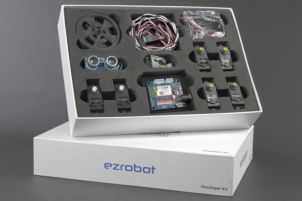
Whether you have the EZ-Robot Developer Kit, Robot Head, Shell-E, or a custom collection of robotics parts, building a robot has never been easier. EZ-Robot and the world-class ARC software empower everyone to make the robot of their dreams. Robot Controllers All EZ-Robots are powered by either the EZ-B v4 Smart Robot Controller or the IoTiny. These powerful robot controllers offer huge capabilities in a very small footprint. Both controllers share the same communication protocol and connection method. The IoTiny is, essentially, a compact version of the EZ-B v4. All connections and uses described in these tutorial steps apply to both the IoTiny and EZ-B v4 users. Of course, the IoTiny has less I/O and no UART. Other than that, they operate the same. IoTiny users may follow lessons in this tutorial section for connecting and using their IoTiny. The EZ-B v4 and IoTiny are amazing tools for building custom DIY robots or teaching old toys new tricks. Watch our team introduce a few robots that they have built using the IoTiny and EZ-B v4 in this Robot Program episode. *Note: This video shows an unboxing of the Developer Kit 1.0. The current version of the Developer Kit (2.0) is powered by an IoTiny instead of an EZ-B and also includes 2 LED lights and some extension wires to help you build larger robots with greater distances between the servos and the controller. Inside the EZ-B v4
With the electronics protected by a stylish plastic shell, the EZ-B v4 brain fits perfectly in your Revolution EZ-Robot and is easily programmed over Wi-Fi using our Software. If you're new to robotics and this next section sounds a little more technical than you understand, don't be worried. Our tutorials will walk you through the connections and functions. EZ-Robot makes it easy for everyone to build and program powerful robots.
As your knowledge grows, each of the terms below will begin to make more sense. The important thing to know is that our controllers are very powerful and they'll help you do incredible things! Technical Specifications The EZ-B v4 boasts:
...all in a compact 2.1" x 2.2" size! EZ-B v4 Port Summary 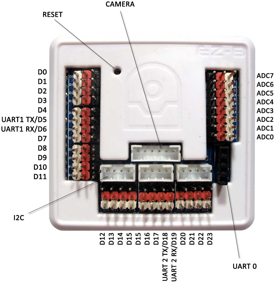
The EZ-B v4 has 24 Digital Ports and 8 Analog Ports. The Digital Ports are labelled D0 through D23, and run down the left side and along the bottom.
The ADC Analog Ports are labelled A0 through A7, and run down the right side. Each port has 3 pins, which are GND (Ground), VCC and Signal. The GND and VCC are for powering the device connected to the port. The Signal pin is connected to the EZ-B Microchip for reading or writing data from Digital or ADC. The GND and VCC pins are not connected to the Microchip, they are only used for powering the peripheral connected to the EZ-B v4. For example, a servo has a 3 wire plug that connects to one of the EZ-B Digital Ports. The wires of a servo connector are GND, VCC and Signal. The GND and VCC provide power to the servo's motor and circuit. The Signal wire carries the information to tell the servo what position to move. *Note: When plugging a servo into a Port on the EZ-B or IoTiny, it's critically important that the black wire plugs into the black pin. The other two white wires will plug into the white and red pins. IoTiny Port Summary 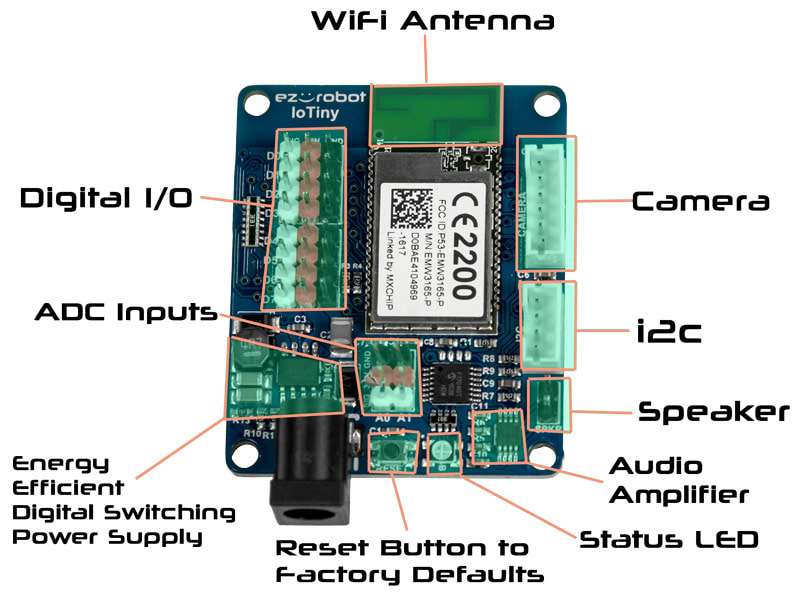
The IoTiny has 8 Digital Ports and 2 Analog Ports. The Digital Ports are labelled D0 through D7. The ADC Analog Ports are labelled A0 through A1.
3 PIN (GVS) Connectors Each port has 3 pins, which are GND (Ground), VCC, and Signal. The GND and VCC are for powering the device connected to the port. The Signal pin is connected to the EZ-B Microchip for reading or writing data from Digital or ADC. The GND and VCC pins are not connected to the Microchip, they are used only for powering the peripheral connected to the IoTiny. For example, a servo has a 3 wire plug that connects to one of the EZ-B Digital Ports. The wires of a servo connector are also GND, VCC, and Signal. The GND and VCC provide power to the servo's motor and circuit. The Signal wire carries the information to tell the servo what position to move. Connecting the Camera The EZ-Robot Camera connects to the EZ-B v4 with a 6 pin cable. Notches on the male connector match the EZ-B's female connector. This prevents the plug from connecting incorrectly. The camera connection is unique, making it easy to identify where to connect. It is impossible to connect the camera cable to the wrong connector, as it only fits in the matching plug.
Connecting Servos & I/O Much like your home theater speakers, the cables of the EZ-B and peripherals are color coded. The BLACK wire on the peripheral (i.e. servo) will connect to match the BLACK pin of the EZ-B connector.
EZ-B v4 Ports Overview Unregulated Power I/O
If you plan on building your own custom robots, it is important that you know how the power pins work, as you may need custom power requirements. The EZ-B v4 does not regulate the power on the I/O pins. This means that if you provide 12V to the EZ-B v4, the I/O pins will output 12V. Of course, this will damage any +5V peripherals that you connect to the EZ-B v4 when using 12V. You must be aware of how much power is being provided to the EZ-B v4 and what you are connecting to the I/O pins. For example, the EZ-Robot Servos do not like power above 7.4 volts - which is why we recommend using an EZ-Robot LiPo battery or Rechargeable AA batteries in the provided holder. If you are wishing to use an alternate power source, please be aware of this message and select a voltage rating that works with your application and peripherals. *Note: The only ports that have regulated power are the Camera, i2c and UART #0 Expansion. Learn Your Port Types
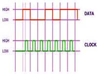
UART Serial (bi-directional)
The V4 UARTx ports are used to connect to Serial TTL devices for both input and output. Contrary to the digital port Serial Output, these peripherals will also receive data into an input buffer as well. The input buffer of each UART is 5,000 Bytes. There are 3 UARTs, the first is the hardware labelled port, second and third are digital pins. These UARTs are controlled using the UARTInit(), UARTWrite(), UARTRead() and UARTAvailable() commands. The speed of these UARTs can be any integer between 1 and 3750000 bps. UART0 TX: Expansion Connector UART0 RX: Expansion Connector UART1 TX: D5 UART1 RX: D6 UART2 TX: D18 UART2 RX: D19 |