|
TABLE OF CONTENTS
Software 1. ARC for Windows PC 2. Example Projects 3. Controls 4. Getting Help with Controls 5. ControlCommand() 6. Virtual Desktops 7. RoboScratch 8. Blockly 9. EZ-Script Mobile Software 1. Create a Mobile App Linear Programming 1. Create a Scene Using RoboScratch (Big Hero Six) 2. Create a Scene using Blockly (Avengers) Logical Programming 1. Programming Concepts (Variables, If/Else, Logic) 2. Counting Up 3. Counting Down Camera Input 1. Introduction to the EZ-B Camera 2. Face Detection with RoboScratch 3. Face Detection with Blockly 4. Face Detection with EZ-Script 5. Color Tracking with Servos 6. Color Tracking with Movement 7. Detecting Multiple Colors 8. Line Following with Roli, AdventureBot and Shell-E 9. Vision - Object Training & Recognition 10. Glyphs to Control Robot Movement 11. Detecting Glyphs & Augmented Reality 12. QR Code Detect 13. Microsoft Cognitive Emotion 14. Microsoft Cognitive Vision Audio Input 1. Speech Recognition RGB Output 1. RGB Animations Positioning 1. Servo Control 2. Introduction to Servo Motors 3. Create a Robot Dance 4. Program Robot to Dab 5. Program Robot to Play Piano 6. MYO Gesture Armband Navigation and Movement 1. Movement Panels 2. Navigating using RoboScratch 3. Navigating using Blockly Creative Applications 1. Customize Your EZ-Robot 2. Control Robot From Twitter 3. Nest Thermostat EZ-B v4 Robot Brain 1. EZ-B v4 Robot Brain Overview 2. DIY Autonomous Robot Vehicle 3. EZ-B v4 and IoTiny Wi-Fi Modes 4. Change WiFi Name 5. Resetting Your EZ-B v4 or IoTiny 6. USB WiFi or Ethernet Adapter Robot Troubleshooting 1. Which Robot are You Using? |
EZ-B v4 Robot Brain OverviewIntroduction
With the electronics protected by a stylish plastic shell, the EZ-B v4 Smart Robot Controller fits in your EZ-Robot or a Power Base. This controller is easily programmed over Wi-Fi from with ARC software (formerly EZ-Builder). Specifications
The EZ-B v4 boasts:
...all in a compact 2.1" x 2.2" size! EZ-B v4 Port Summary 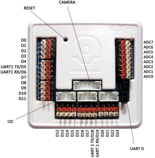
The EZ-B v4 has 24 Digital Ports and 8 Analog Ports. The Digital Ports are labelled D0 through D23, and run down the left side and along the bottom.
The ADC Analog Ports are labelled A0 through A7, and run down the right side. Each port has 3 pins, which are GND (Ground), VCC and Signal. The GND and VCC are for powering the device connected to the port. The Signal pin is connected to the EZ-B Microchip for reading or writing data from Digital or ADC. The GND and VCC pins are not connected to the Microchip, they are used only for powering the peripheral connected to the EZ-B v4. For example, a servo has a 3 wire plug that connects to one of the EZ-B Digital Ports. The wires of a servo connector are GND, VCC and Signal. The GND and VCC provide power to the servo's motor and circuit. The Signal wire carries the information to tell the servo what position to move. Connecting the Camera The EZ-Robot Camera connects to the EZ-B v4 with a 6 pin cable. Notches on the male connector match the EZ-B's female connector. This prevents the plug from connecting incorrectly. The camera connection is unique, making it easy to identify where to connect. It is impossible to connect the camera cable to the wrong connector, as it only fits in the matching plug.
Connecting Servos & I/O Much like your home theater speakers, the cables of the EZ-B and peripherals are color coded. The BLACK wire on the peripheral (i.e. servo) will connect to match the BLACK pin of the EZ-B connector.
EZ-B v4 Ports Overview Learn Your Port Types
Output is writing to a port: When a port has its digital value set to True, then a +3.3 voltage will be outputted on that port. If the port has its digital value set to False, then the port will be GND.
Input is reading from a port: You can read the value of a specific port. This is how you can check for voltage, On or Off. Any voltage above GND (and below +5 volts) will be returned as True, a short to GND will be returned as False. Some examples of peripheral devices for digital ports are Switches, Servos, Ultrasonic Distance Sensors, and Buttons.
Reading Relative Voltage: The returned value will be between 0-255 in 8 bit mode and 0-4095 in 12 bit mode. These values represent the input voltage on the specified port. The value will be relative to the input voltage that will between 0 and 5 volts. Example in 8 bit mode: Value 0 = 0 Volts, Value 127 = 2.5 Volts, Value 255 = 5 Volts.
Reading Absolute Voltage: Returns the value in actual volts on the specified port. Example peripherals for analog input are Sharp GP2 Analog Distance Sensors, Pressure Sensors, Light Sensors, Sound Sensors, Color Sensors, and reading voltages.
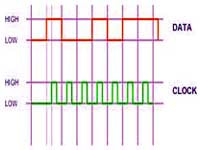
The Sender and Receiver need to be configured for the baud rate (speed) in which the data will be transmitted. Common baud rate speeds are 300bps, 4800bps, 9600bps, 19200bps, 38400bps, 57600bps and 115200bps.
There are also 3 high speed UART ports on the EZ-B which allow transmit and receive abilities. The buffer size for input on each of the 3 high speed UART ports is 5,000 Bytes. Example peripherals for serial communication are LCD Screens, Motor Controllers, Servo Controllers, Computer Communication, Arduino Communication, iRobot Roomba, and more.
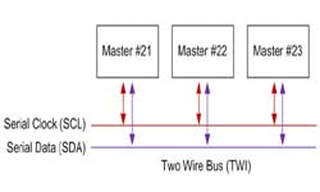
I2C devices can be chained together in a network formation. Each device is given a unique address. The EZ-B v4 has three I2C ports which provide both signal wires and +3.3v power.
Example peripherals for I2C communication are LCD Screens, I2C enabled Servos, BlinkM Multicolor LEDs, and more. |